PCB Test & Measurement Seite 72
Hinweis: Dies ist eine maschinenlesbare No-Flash Ansicht.Klicken Sie hier um zur Online-Version zu gelangen.
Inhalt
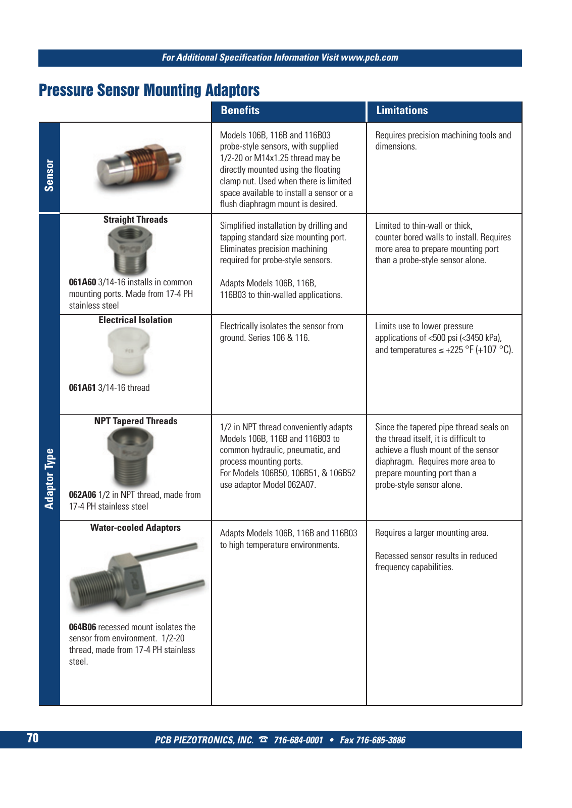
PCB PIEZOTRONICS INC 716 684 0001 Fax 716 685 3886 For Additional Specification Information Visit www pcb com 70 Electrically isolates the sensor from ground Series 106 116 Limits use to lower pressure applications of 500 psi 3450 kPa and temperatures 225 F 107 C 064B06 recessed mount isolates the sensor from environment 1 2 20 thread made from 17 4 PH stainless steel Ad ap to r T yp e Benefits Limitations Models 106B 116B and 116B03 probe style sensors with supplied 1 2 20 or M14x1 25 thread may be directly mounted using the floating clamp nut Used when there is limited space available to install a sensor or a flush diaphragm mount is desired Se ns or Requires precision machining tools and dimensions Simplified installation by drilling and tapping standard size mounting port Eliminates precision machining required for probe style sensors Adapts Models 106B 116B 116B03 to thin walled applications Limited to thin wall or thick counter bored walls to install Requires more area to prepare mounting port than a probe style sensor alone Adapts Models 106B 116B and 116B03 to high temperature environments 1 2 in NPT thread conveniently adapts Models 106B 116B and 116B03 to common hydraulic pneumatic and process mounting ports For Models 106B50 106B51 106B52 use adaptor Model 062A07 Requires a larger mounting area Recessed sensor results in reduced frequency capabilities Since the tapered pipe thread seals on the thread itself it is difficult to achieve a flush mount of the sensor diaphragm Requires more area to prepare mounting port than a probe style sensor alone 061A61 3 14 16 thread Straight Threads NPT Tapered Threads Water cooled Adaptors Electrical Isolation Pressure Sensor Mounting Adaptors 062A06 1 2 in NPT thread made from 17 4 PH stainless steel 061A60 3 14 16 installs in common mounting ports Made from 17 4 PH stainless steel 5 T Mcatalog 2011 Seite 65 82 A4 F G500 21 04 11 15 35 Seite 70