PCB Test & Measurement Seite 7
Hinweis: Dies ist eine maschinenlesbare No-Flash Ansicht.Klicken Sie hier um zur Online-Version zu gelangen.
Inhalt
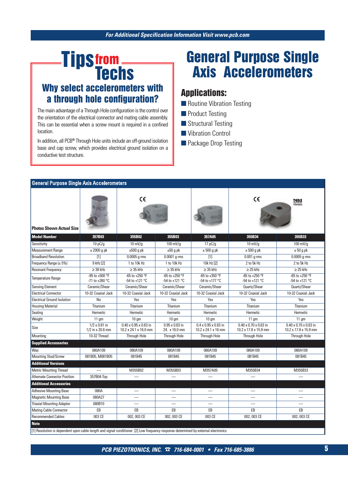
For Additional Specification Information Visit www pcb com PCB PIEZOTRONICS INC 716 684 0001 Fax 716 685 3886 5 General Purpose Single Axis Accelerometers General Purpose Single Axis Accelerometers Model Number 357B03 355B02 355B03 357A05 355B34 355B33 Sensitivity 10 pC g 10 mV g 100 mV g 17 pC g 10 mV g 100 mV g Measurement Range 2000 g pk 500 g pk 50 g pk 500 g pk 500 g pk 50 g pk Broadband Resolution 1 0 0005 g rms 0 0001 g rms 1 0 001 g rms 0 0005 g rms Frequency Range 5 9 kHz 2 1 to 10k Hz 1 to 10k Hz 10k Hz 2 2 to 5k Hz 2 to 5k Hz Resonant Frequency 38 kHz 35 kHz 35 kHz 35 kHz 25 kHz 25 kHz Temperature Range 95 to 500 F 71 to 260 C 65 to 250 F 54 to 121 C 65 to 250 F 54 to 121 C 65 to 350 F 54 to 177 C 65 to 250 F 54 to 121 C 65 to 250 F 54 to 121 C Sensing Element Ceramic Shear Ceramic Shear Ceramic Shear Ceramic Shear Quartz Shear Quartz Shear Electrical Connector 10 32 Coaxial Jack 10 32 Coaxial Jack 10 32 Coaxial Jack 10 32 Coaxial Jack 10 32 Coaxial Jack 10 32 Coaxial Jack Electrical Ground Isolation No Yes Yes Yes Yes Yes Housing Material Titanium Titanium Titanium Titanium Titanium Titanium Sealing Hermetic Hermetic Hermetic Hermetic Hermetic Hermetic Weight 11 gm 10 gm 10 gm 10 gm 11 gm 11 gm Size 1 2 x 0 81 in1 2 in x 20 6 mm 0 40 x 0 95 x 0 63 in 10 2 x 24 1 x 16 0 mm 0 95 x 0 63 in 24 x 16 0 mm 0 4 x 0 95 x 0 63 in 10 2 x 24 1 x 16 mm 0 40 x 0 70 x 0 63 in 10 2 x 17 8 x 15 9 mm 0 40 x 0 70 x 0 63 in 10 2 x 17 8 x 15 9 mm Mounting 10 32 Thread Through Hole Through Hole Through Hole Through Hole Through Hole Supplied Accessories Wax 080A109 080A109 080A109 080A109 080A109 080A109 Mounting Stud Screw 081B05 M081B05 081B45 081B45 081B45 081B45 081B45 Additional Versions Metric Mounting Thread M355B02 M355B03 M357A05 M355B34 M355B33 Alternate Connector Position 357B04 Top Additional Accessories Adhesive Mounting Base 080A Magnetic Mounting Base 080A27 Triaxial Mounting Adaptor 080B10 Mating Cable Connector EB EB EB EB EB EB Recommended Cables 003 CE 002 003 CE 002 003 CE 003 CE 002 003 CE 002 003 CE Note 1 Resolution is dependent upon cable length and signal conditioner 2 Low frequency response determined by external electronics Photos Shown Actual Size The main advantage of a Through Hole configuration is the control over the orientation of the electrical connector and mating cable assembly This can be essential when a screw mount is required in a confined location In addition all PCB Through Hole units include an off ground isolation base and cap screw which provides electrical ground isolation on a conductive test structure Tipsfrom Techs Why select accelerometers with a through hole configuration Applications Routine Vibration Testing Product Testing Structural Testing Vibration Control Package Drop Testing 1 T Mcatalog 2011 S 1 16 SYN F G500 21 04 11 17 54 Seite 5