PCB Test & Measurement Seite 6
Hinweis: Dies ist eine maschinenlesbare No-Flash Ansicht.Klicken Sie hier um zur Online-Version zu gelangen.
Inhalt
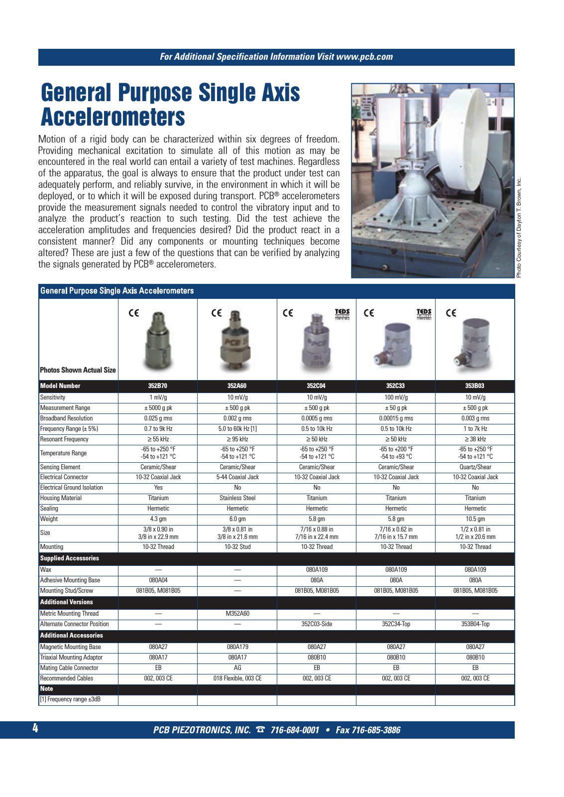
PCB PIEZOTRONICS INC 716 684 0001 Fax 716 685 3886 For Additional Specification Information Visit www pcb com 4 General Purpose Single Axis Accelerometers General Purpose Single Axis Accelerometers Model Number 352B70 352A60 352C04 352C33 353B03 Sensitivity 1 mV g 10 mV g 10 mV g 100 mV g 10 mV g Measurement Range 5000 g pk 500 g pk 500 g pk 50 g pk 500 g pk Broadband Resolution 0 025 g rms 0 002 g rms 0 0005 g rms 0 00015 g rms 0 003 g rms Frequency Range 5 0 7 to 9k Hz 5 0 to 60k Hz 1 0 5 to 10k Hz 0 5 to 10k Hz 1 to 7k Hz Resonant Frequency 55 kHz 95 kHz 50 kHz 50 kHz 38 kHz Temperature Range 65 to 250 F 54 to 121 C 65 to 250 F 54 to 121 C 65 to 250 F 54 to 121 C 65 to 200 F 54 to 93 C 65 to 250 F 54 to 121 C Sensing Element Ceramic Shear Ceramic Shear Ceramic Shear Ceramic Shear Quartz Shear Electrical Connector 10 32 Coaxial Jack 5 44 Coaxial Jack 10 32 Coaxial Jack 10 32 Coaxial Jack 10 32 Coaxial Jack Electrical Ground Isolation Yes No No No No Housing Material Titanium Stainless Steel Titanium Titanium Titanium Sealing Hermetic Hermetic Hermetic Hermetic Hermetic Weight 4 3 gm 6 0 gm 5 8 gm 5 8 gm 10 5 gm Size 3 8 x 0 90 in3 8 in x 22 9 mm 3 8 x 0 81 in 3 8 in x 21 6 mm 7 16 x 0 88 in 7 16 in x 22 4 mm 7 16 x 0 62 in 7 16 in x 15 7 mm 1 2 x 0 81 in 1 2 in x 20 6 mm Mounting 10 32 Thread 10 32 Stud 10 32 Thread 10 32 Thread 10 32 Thread Supplied Accessories Wax 080A109 080A109 080A109 Adhesive Mounting Base 080A04 080A 080A 080A Mounting Stud Screw 081B05 M081B05 081B05 M081B05 081B05 M081B05 081B05 M081B05 Additional Versions Metric Mounting Thread M352A60 Alternate Connector Position 352C03 Side 352C34 Top 353B04 Top Additional Accessories Magnetic Mounting Base 080A27 080A179 080A27 080A27 080A27 Triaxial Mounting Adaptor 080A17 080A17 080B10 080B10 080B10 Mating Cable Connector EB AG EB EB EB Recommended Cables 002 003 CE 018 Flexible 003 CE 002 003 CE 002 003 CE 002 003 CE Note 1 Frequency range 3dB Photos Shown Actual Size Motion of a rigid body can be characterized within six degrees of freedom Providing mechanical excitation to simulate all of this motion as may be encountered in the real world can entail a variety of test machines Regardless of the apparatus the goal is always to ensure that the product under test can adequately perform and reliably survive in the environment in which it will be deployed or to which it will be exposed during transport PCB accelerometers provide the measurement signals needed to control the vibratory input and to analyze the product s reaction to such testing Did the test achieve the acceleration amplitudes and frequencies desired Did the product react in a consistent manner Did any components or mounting techniques become altered These are just a few of the questions that can be verified by analyzing the signals generated by PCB accelerometers Ph ot o C ou rte sy o f D ay to n T B ro w n In c 1 T Mcatalog 2011 S 1 16 SYN F G500 21 04 11 17 54 Seite 4