PCB Test & Measurement Seite 166
Hinweis: Dies ist eine maschinenlesbare No-Flash Ansicht.Klicken Sie hier um zur Online-Version zu gelangen.
Inhalt
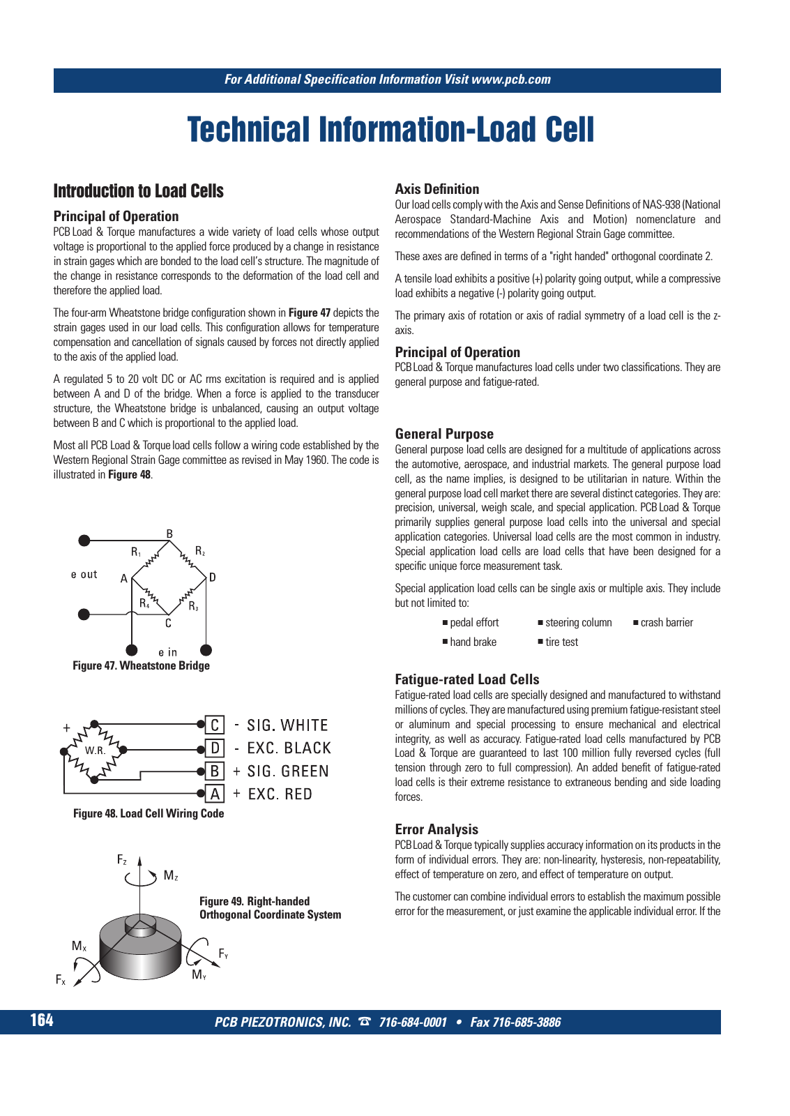
Technical Information Load Cell PCB PIEZOTRONICS INC 716 684 0001 Fax 716 685 3886 For Additional Specification Information Visit www pcb com 164 Figure 47 Wheatstone Bridge Figure 48 Load Cell Wiring Code Figure 49 Right handed Orthogonal Coordinate System Introduction to Load Cells Principal of Operation PCB Load Torque manufactures a wide variety of load cells whose output voltage is proportional to the applied force produced by a change in resistance in strain gages which are bonded to the load cell s structure The magnitude of the change in resistance corresponds to the deformation of the load cell and therefore the applied load The four arm Wheatstone bridge configuration shown in Figure 47 depicts the strain gages used in our load cells This configuration allows for temperature compensation and cancellation of signals caused by forces not directly applied to the axis of the applied load A regulated 5 to 20 volt DC or AC rms excitation is required and is applied between A and D of the bridge When a force is applied to the transducer structure the Wheatstone bridge is unbalanced causing an output voltage between B and C which is proportional to the applied load Most all PCB Load Torque load cells follow a wiring code established by the Western Regional Strain Gage committee as revised in May 1960 The code is illustrated in Figure 48 Axis Definition Our load cells comply with the Axis and Sense Definitions of NAS 938 National Aerospace Standard Machine Axis and Motion nomenclature and recommendations of the Western Regional Strain Gage committee These axes are defined in terms of a right handed orthogonal coordinate 2 A tensile load exhibits a positive polarity going output while a compressive load exhibits a negative polarity going output The primary axis of rotation or axis of radial symmetry of a load cell is the z axis Principal of Operation PCBLoad Torque manufactures load cells under two classifications They are general purpose and fatigue rated General Purpose General purpose load cells are designed for a multitude of applications across the automotive aerospace and industrial markets The general purpose load cell as the name implies is designed to be utilitarian in nature Within the general purpose load cell market there are several distinct categories They are precision universal weigh scale and special application PCB Load Torque primarily supplies general purpose load cells into the universal and special application categories Universal load cells are the most common in industry Special application load cells are load cells that have been designed for a specific unique force measurement task Special application load cells can be single axis or multiple axis They include but not limited to pedal effort steering column crash barrier hand brake tire test Fatigue rated Load Cells Fatigue rated load cells are specially designed and manufactured to withstand millions of cycles They are manufactured using premium fatigue resistant steel or aluminum and special processing to ensure mechanical and electrical integrity as well as accuracy Fatigue rated load cells manufactured by PCB Load Torque are guaranteed to last 100 million fully reversed cycles full tension through zero to full compression An added benefit of fatigue rated load cells is their extreme resistance to extraneous bending and side loading forces Error Analysis PCBLoad Torque typically supplies accuracy information on its products in the form of individual errors They are non linearity hysteresis non repeatability effect of temperature on zero and effect of temperature on output The customer can combine individual errors to establish the maximum possible error for the measurement or just examine the applicable individual error If the 9 T Mcatalog 2011 Seite 125 166 SYN G500 21 04 11 18 04 Seite 170