PCB Test & Measurement Seite 162
Hinweis: Dies ist eine maschinenlesbare No-Flash Ansicht.Klicken Sie hier um zur Online-Version zu gelangen.
Inhalt
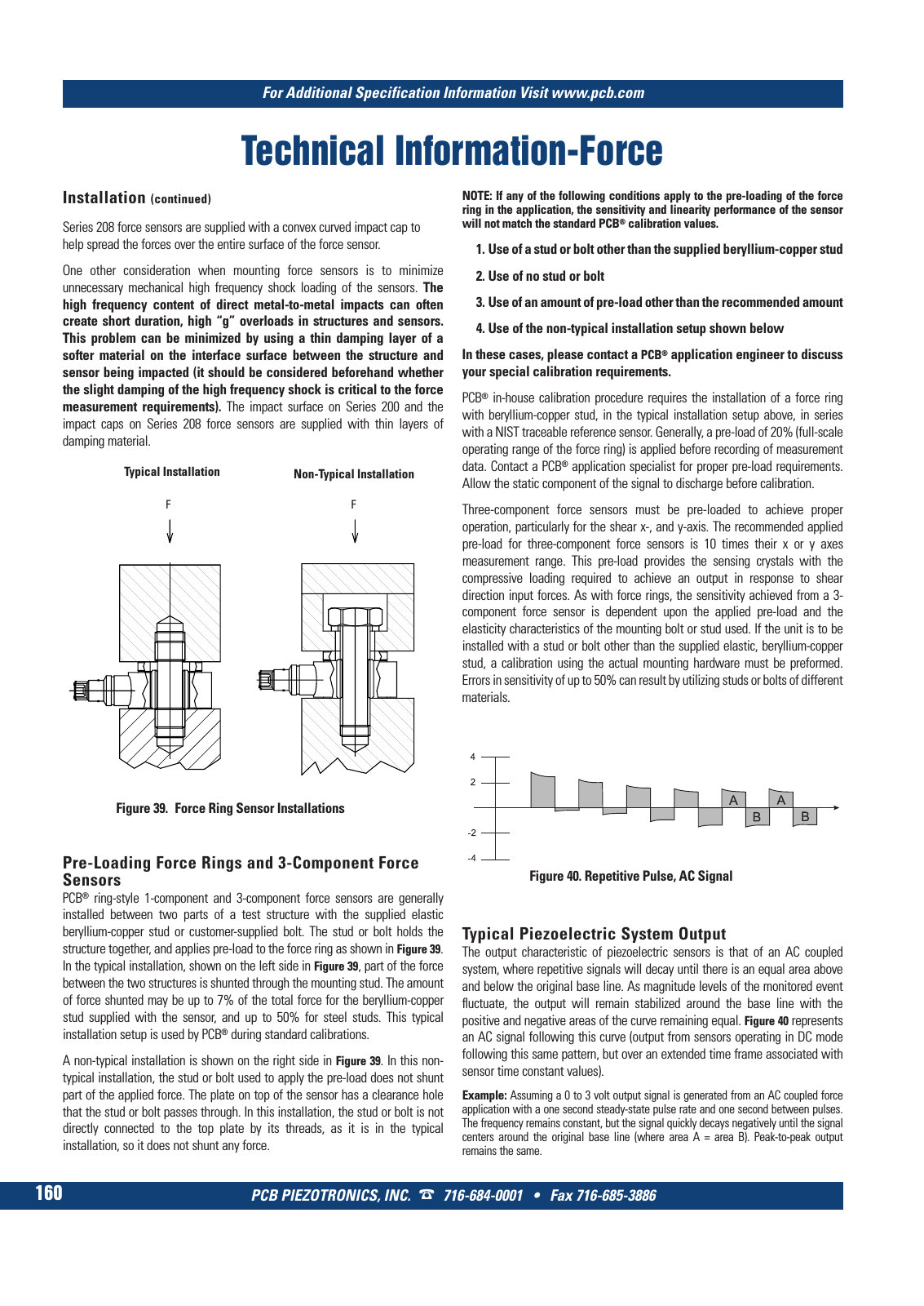
Technical Information Force PCB PIEZOTRONICS INC 716 684 0001 Fax 716 685 3886 For Additional Specification Information Visit www pcb com 160 Installation continued Series 208 force sensors are supplied with a convex curved impact cap to help spread the forces over the entire surface of the force sensor One other consideration when mounting force sensors is to minimize unnecessary mechanical high frequency shock loading of the sensors The high frequency content of direct metal to metal impacts can often create short duration high g overloads in structures and sensors This problem can be minimized by using a thin damping layer of a softer material on the interface surface between the structure and sensor being impacted it should be considered beforehand whether the slight damping of the high frequency shock is critical to the force measurement requirements The impact surface on Series 200 and the impact caps on Series 208 force sensors are supplied with thin layers of damping material Typical Installation Non Typical Installation Figure 39 Force Ring Sensor Installations F F Typical Piezoelectric System Output The output characteristic of piezoelectric sensors is that of an AC coupled system where repetitive signals will decay until there is an equal area above and below the original base line As magnitude levels of the monitored event fluctuate the output will remain stabilized around the base line with the positive and negative areas of the curve remaining equal Figure 40 represents an AC signal following this curve output from sensors operating in DC mode following this same pattern but over an extended time frame associated with sensor time constant values Example Assuming a 0 to 3 volt output signal is generated from an AC coupled force application with a one second steady state pulse rate and one second between pulses The frequency remains constant but the signal quickly decays negatively until the signal centers around the original base line where area A area B Peak to peak output remains the same Figure 40 Repetitive Pulse AC Signal Pre Loading Force Rings and 3 Component Force Sensors PCB ring style 1 component and 3 component force sensors are generally installed between two parts of a test structure with the supplied elastic beryllium copper stud or customer supplied bolt The stud or bolt holds the structure together and applies pre load to the force ring as shown in Figure 39 In the typical installation shown on the left side in Figure 39 part of the force between the two structures is shunted through the mounting stud The amount of force shunted may be up to 7 of the total force for the beryllium copper stud supplied with the sensor and up to 50 for steel studs This typical installation setup is used by PCB during standard calibrations A non typical installation is shown on the right side in Figure 39 In this non typical installation the stud or bolt used to apply the pre load does not shunt part of the applied force The plate on top of the sensor has a clearance hole that the stud or bolt passes through In this installation the stud or bolt is not directly connected to the top plate by its threads as it is in the typical installation so it does not shunt any force NOTE If any of the following conditions apply to the pre loading of the force ring in the application the sensitivity and linearity performance of the sensor will not match the standard PCB calibration values 1 Use of a stud or bolt other than the supplied beryllium copper stud 2 Use of no stud or bolt 3 Use of an amount of pre load other than the recommended amount 4 Use of the non typical installation setup shown below In these cases please contact a PCB application engineer to discuss your special calibration requirements PCB in house calibration procedure requires the installation of a force ring with beryllium copper stud in the typical installation setup above in series with a NIST traceable reference sensor Generally a pre load of 20 full scale operating range of the force ring is applied before recording of measurement data Contact a PCB application specialist for proper pre load requirements Allow the static component of the signal to discharge before calibration Three component force sensors must be pre loaded to achieve proper operation particularly for the shear x and y axis The recommended applied pre load for three component force sensors is 10 times their x or y axes measurement range This pre load provides the sensing crystals with the compressive loading required to achieve an output in response to shear direction input forces As with force rings the sensitivity achieved from a 3 component force sensor is dependent upon the applied pre load and the elasticity characteristics of the mounting bolt or stud used If the unit is to be installed with a stud or bolt other than the supplied elastic beryllium copper stud a calibration using the actual mounting hardware must be preformed Errors in sensitivity of up to 50 can result by utilizing studs or bolts of different materials 9 T Mcatalog 2011 Seite 125 166 SYN G500 21 04 11 18 04 Seite 166