PCB Test & Measurement Seite 161
Hinweis: Dies ist eine maschinenlesbare No-Flash Ansicht.Klicken Sie hier um zur Online-Version zu gelangen.
Inhalt
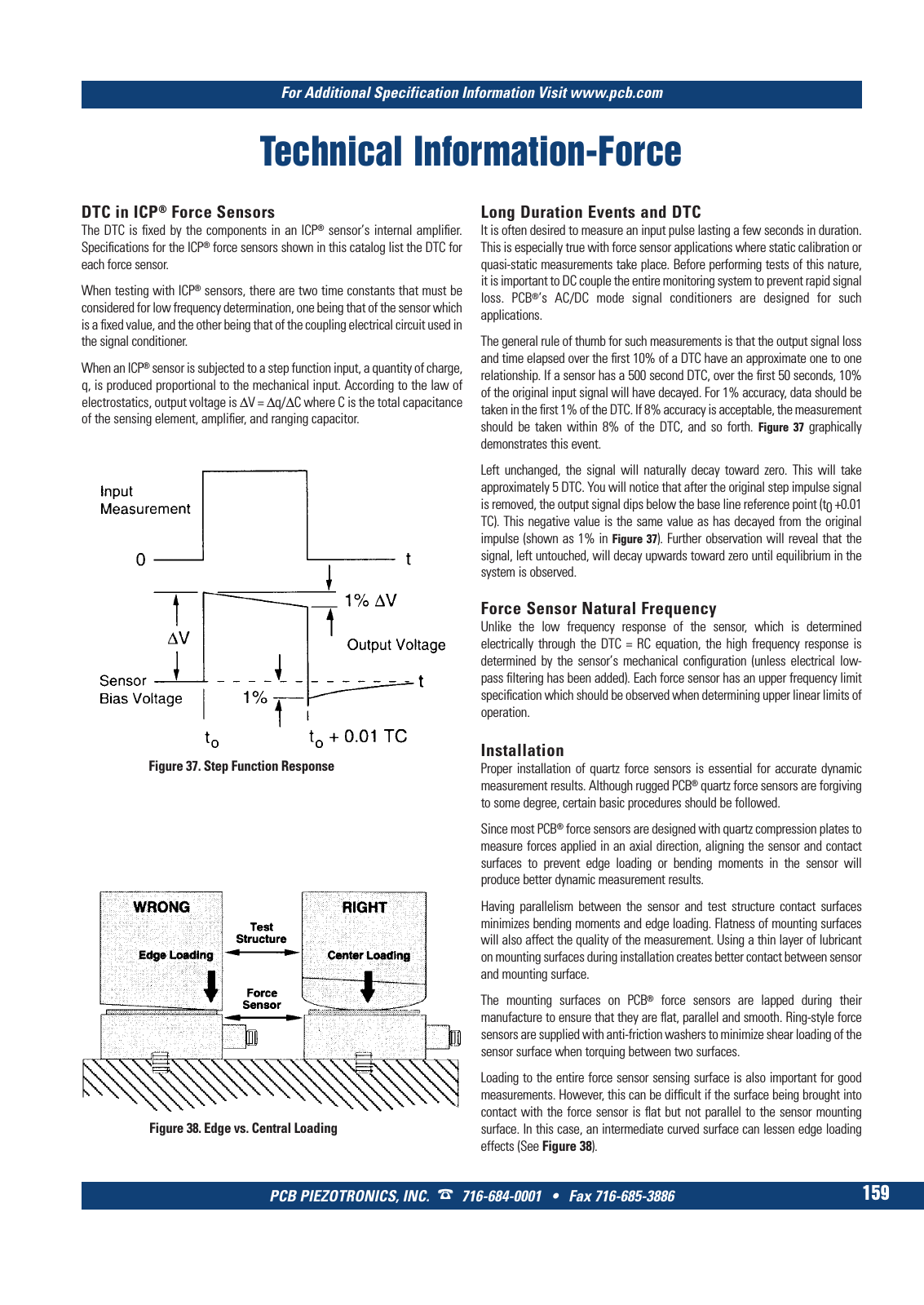
For Additional Specification Information Visit www pcb com PCB PIEZOTRONICS INC 716 684 0001 Fax 716 685 3886 159 Technical Information Force DTC in ICP Force Sensors The DTC is fixed by the components in an ICP sensor s internal amplifier Specifications for the ICP force sensors shown in this catalog list the DTC for each force sensor When testing with ICP sensors there are two time constants that must be considered for low frequency determination one being that of the sensor which is a fixed value and the other being that of the coupling electrical circuit used in the signal conditioner When an ICP sensor is subjected to a step function input a quantity of charge q is produced proportional to the mechanical input According to the law of electrostatics output voltage is V q C where C is the total capacitance of the sensing element amplifier and ranging capacitor Figure 37 Step Function Response Figure 38 Edge vs Central Loading Long Duration Events and DTC It is often desired to measure an input pulse lasting a few seconds in duration This is especially true with force sensor applications where static calibration or quasi static measurements take place Before performing tests of this nature it is important to DC couple the entire monitoring system to prevent rapid signal loss PCB s AC DC mode signal conditioners are designed for such applications The general rule of thumb for such measurements is that the output signal loss and time elapsed over the first 10 of a DTC have an approximate one to one relationship If a sensor has a 500 second DTC over the first 50 seconds 10 of the original input signal will have decayed For 1 accuracy data should be taken in the first 1 of the DTC If 8 accuracy is acceptable the measurement should be taken within 8 of the DTC and so forth Figure 37 graphically demonstrates this event Left unchanged the signal will naturally decay toward zero This will take approximately 5 DTC You will notice that after the original step impulse signal is removed the output signal dips below the base line reference point t0 0 01 TC This negative value is the same value as has decayed from the original impulse shown as 1 in Figure 37 Further observation will reveal that the signal left untouched will decay upwards toward zero until equilibrium in the system is observed Force Sensor Natural Frequency Unlike the low frequency response of the sensor which is determined electrically through the DTC RC equation the high frequency response is determined by the sensor s mechanical configuration unless electrical low pass filtering has been added Each force sensor has an upper frequency limit specification which should be observed when determining upper linear limits of operation Installation Proper installation of quartz force sensors is essential for accurate dynamic measurement results Although rugged PCB quartz force sensors are forgiving to some degree certain basic procedures should be followed Since most PCB force sensors are designed with quartz compression plates to measure forces applied in an axial direction aligning the sensor and contact surfaces to prevent edge loading or bending moments in the sensor will produce better dynamic measurement results Having parallelism between the sensor and test structure contact surfaces minimizes bending moments and edge loading Flatness of mounting surfaces will also affect the quality of the measurement Using a thin layer of lubricant on mounting surfaces during installation creates better contact between sensor and mounting surface The mounting surfaces on PCB force sensors are lapped during their manufacture to ensure that they are flat parallel and smooth Ring style force sensors are supplied with anti friction washers to minimize shear loading of the sensor surface when torquing between two surfaces Loading to the entire force sensor sensing surface is also important for good measurements However this can be difficult if the surface being brought into contact with the force sensor is flat but not parallel to the sensor mounting surface In this case an intermediate curved surface can lessen edge loading effects See Figure 38 9 T Mcatalog 2011 Seite 125 166 SYN G500 21 04 11 18 04 Seite 165