PCB Test & Measurement Seite 159
Hinweis: Dies ist eine maschinenlesbare No-Flash Ansicht.Klicken Sie hier um zur Online-Version zu gelangen.
Inhalt
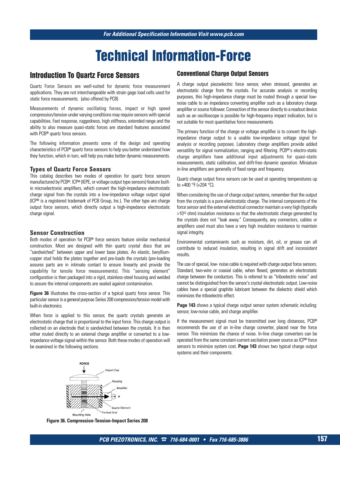
For Additional Specification Information Visit www pcb com PCB PIEZOTRONICS INC 716 684 0001 Fax 716 685 3886 157 Technical Information Force Figure 36 Compression Tension Impact Series 208 Quartz Force Sensors are well suited for dynamic force measurement applications They are not interchangeable with strain gage load cells used for static force measurements also offered by PCB Measurements of dynamic oscillating forces impact or high speed compression tension under varying conditions may require sensors with special capabilities Fast response ruggedness high stiffness extended range and the ability to also measure quasi static forces are standard features associated with PCB quartz force sensors The following information presents some of the design and operating characteristics of PCB quartz force sensors to help you better understand how they function which in turn will help you make better dynamic measurements Types of Quartz Force Sensors This catalog describes two modes of operation for quartz force sensors manufactured by PCB ICP IEPE or voltage output type sensors feature built in microelectronic amplifiers which convert the high impedance electrostatic charge signal from the crystals into a low impedance voltage output signal ICP is a registered trademark of PCB Group Inc The other type are charge output force sensors which directly output a high impedance electrostatic charge signal Introduction To Quartz Force Sensors Sensor Construction Both modes of operation for PCB force sensors feature similar mechanical construction Most are designed with thin quartz crystal discs that are sandwiched between upper and lower base plates An elastic beryllium copper stud holds the plates together and pre loads the crystals pre loading assures parts are in intimate contact to ensure linearity and provide the capability for tensile force measurements This sensing element configuration is then packaged into a rigid stainless steel housing and welded to assure the internal components are sealed against contamination Figure 36 illustrates the cross section of a typical quartz force sensor This particular sensor is a general purpose Series 208 compression tension model with built in electronics When force is applied to this sensor the quartz crystals generate an electrostatic charge that is propor tional to the input force This charge output is collected on an electrode that is sandwiched between the crystals It is then either routed directly to an external charge amplifier or converted to a low impedance voltage signal within the sensor Both these modes of operation will be examined in the following sections Conventional Charge Output Sensors A charge output piezoelectric force sensor when stressed generates an electrostatic charge from the crystals For accurate analysis or recording purposes this high impedance charge must be routed through a special low noise cable to an impedance converting amplifier such as a laboratory charge amplifier or source follower Connection of the sensor directly to a readout device such as an oscilloscope is possible for high frequency impact indication but is not suitable for most quantitative force measurements The primary function of the charge or voltage amplifier is to convert the high impedance charge output to a usable low impedance voltage signal for analysis or recording purposes Laboratory charge amplifiers provide added versatility for signal normalization ranging and filtering PCB s electro static charge amplifiers have additional input adjustments for quasi static measurements static calibration and drift free dynamic operation Miniature in line amplifiers are generally of fixed range and frequency Quartz charge output force sensors can be used at operating temperatures up to 400 F 204 C When considering the use of charge output systems remember that the output from the crystals is a pure electrostatic charge The internal components of the force sensor and the external electrical connector maintain a very high typically 1012 ohm insulation resistance so that the electrostatic charge generated by the crystals does not leak away Consequently any connectors cables or amplifiers used must also have a very high insulation resistance to maintain signal integrity Environmental contaminants such as moisture dirt oil or grease can all contribute to reduced insulation resulting in signal drift and inconsistent results The use of special low noise cable is required with charge output force sensors Standard two wire or coaxial cable when flexed generates an electrostatic charge between the conductors This is referred to as triboelectric noise and cannot be distinguished from the sensor s crystal electrostatic output Low noise cables have a special graphite lubricant between the dielectric shield which minimizes the triboelectric effect Page 143 shows a typical charge output sensor system schematic including sensor low noise cable and charge amplifier If the measurement signal must be transmitted over long distances PCB recommends the use of an in line charge converter placed near the force sensor This minimizes the chance of noise In line charge converters can be operated from the same constant current excitation power source as ICP force sensors to minimize system cost Page 143 shows two typical charge output systems and their components 9 T Mcatalog 2011 Seite 125 166 SYN G500 21 04 11 18 04 Seite 163