PCB Test & Measurement Seite 154
Hinweis: Dies ist eine maschinenlesbare No-Flash Ansicht.Klicken Sie hier um zur Online-Version zu gelangen.
Inhalt
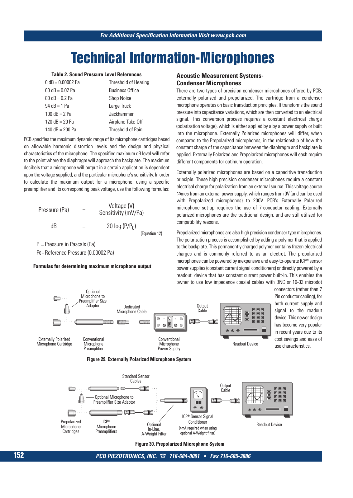
PCB PIEZOTRONICS INC 716 684 0001 Fax 716 685 3886 For Additional Specification Information Visit www pcb com 152 Technical Information Microphones Table 2 Sound Pressure Level References 0 dB 0 00002 Pa Threshold of Hearing 60 dB 0 02 Pa Business Office 80 dB 0 2 Pa Shop Noise 94 dB 1 Pa Large Truck 100 dB 2 Pa Jackhammer 120 dB 20 Pa Airplane Take Off 140 dB 200 Pa Threshold of Pain PCB specifies the maximum dynamic range of its microphone cartridges based on allowable harmonic distortion levels and the design and physical characteristics of the microphone The specified maximum dB level will refer to the point where the diaphragm will approach the backplate The maximum decibels that a microphone will output in a certain application is dependent upon the voltage supplied and the particular microphone s sensitivity In order to calculate the maximum output for a microphone using a specific preamplifier and its corresponding peak voltage use the following formulas Pressure Pa Voltage V Sensitivity mV Pa dB 20 log P P0 P Pressure in Pascals Pa P0 Reference Pressure 0 00002 Pa Formulas for determining maximum microphone output Acoustic Measurement Systems Condenser Microphones There are two types of precision condenser microphones offered by PCB externally polarized and prepolarized The cartridge from a condenser microphone operates on basic transduction principles It transforms the sound pressure into capacitance variations which are then converted to an electrical signal This conversion process requires a constant electrical charge polarization voltage which is either applied by a by a power supply or built into the microphone Externally Polarized microphones will differ when compared to the Prepolarized microphones in the relationship of how the constant charge of the capacitance between the diaphragm and backplate is applied Externally Polarized and Prepolarized microphones will each require different components for optimum operation Externally polarized microphones are based on a capacitive transduction principle These high precision condenser microphones require a constant electrical charge for polarization from an external source This voltage source comes from an external power supply which ranges from 0V and can be used with Prepolarized microphones to 200V PCB s Externally Polarized microphone set up requires the use of 7 conductor cabling Externally polarized microphones are the traditional design and are still utilized for compatibility reasons Prepolarized microphones are also high precision condenser type microphones The polarization process is accomplished by adding a polymer that is applied to the backplate This permanently charged polymer contains frozen electrical charges and is commonly referred to as an electret The prepolarized microphones can be powered by inexpensive and easy to operate ICP sensor power supplies constant current signal conditioners or directly powered by a readout device that has constant current power built in This enables the owner to use low impedance coaxial cables with BNC or 10 32 microdot connectors rather than 7 Pin conductor cabling for both current supply and signal to the readout device This newer design has become very popular in recent years due to its cost savings and ease of use characteristics Externally Polarized Microphone Cartridge Conventional Microphone Preamplifier Readout Device Optional Microphone to Preamplifier Size Adaptor Dedicated Microphone Cable Output Cable Conventional Microphone Power Supply Figure 29 Externally Polarized Microphone System Figure 30 Prepolarized Microphone System Equation 12 Prepolarized Microphone Cartridges ICP Microphone Preamplifiers Optional In Line A Weight Filter Readout Device Optional Microphone to Preamplifier Size Adaptor Standard Sensor Cables Output Cable ICP Sensor Signal Conditioner 4mA required when using optional A Weight filter 9 T Mcatalog 2011 Seite 125 166 SYN G500 21 04 11 18 04 Seite 158