PCB Test & Measurement Seite 151
Hinweis: Dies ist eine maschinenlesbare No-Flash Ansicht.Klicken Sie hier um zur Online-Version zu gelangen.
Inhalt
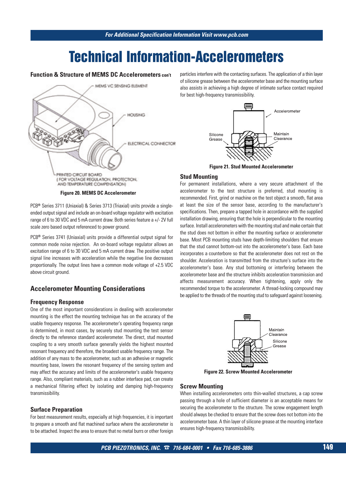
For Additional Specification Information Visit www pcb com PCB PIEZOTRONICS INC 716 684 0001 Fax 716 685 3886 149 Technical Information Accelerometers Figure 20 MEMS DC Accelerometer Accelerometer Mounting Considerations Frequency Response One of the most important considerations in dealing with accelerometer mounting is the effect the mounting technique has on the accuracy of the usable frequency response The accelerometer s operating frequency range is determined in most cases by securely stud mounting the test sensor directly to the reference standard accelerometer The direct stud mounted coupling to a very smooth surface generally yields the highest mounted resonant frequency and therefore the broadest usable frequency range The addition of any mass to the accelerometer such as an adhesive or magnetic mounting base lowers the resonant frequency of the sensing system and may affect the accuracy and limits of the accelerometer s usable frequency range Also compliant materials such as a rubber interface pad can create a mechanical filtering effect by isolating and damping high frequency transmissibility Surface Preparation For best measurement results especially at high frequencies it is important to prepare a smooth and flat machined surface where the accelerometer is to be attached Inspect the area to ensure that no metal burrs or other foreign particles interfere with the contacting surfaces The application of a thin layer of silicone grease between the accelerometer base and the mounting surface also assists in achieving a high degree of intimate surface contact required for best high frequency transmissibility Stud Mounting For permanent installations where a very secure attachment of the accelerometer to the test structure is preferred stud mounting is recommended First grind or machine on the test object a smooth flat area at least the size of the sensor base according to the manufacturer s specifications Then prepare a tapped hole in accordance with the supplied installation drawing ensuring that the hole is perpendicular to the mounting surface Install accelerometers with the mounting stud and make certain that the stud does not bottom in either the mounting surface or accelerometer base Most PCB mounting studs have depth limiting shoulders that ensure that the stud cannot bottom out into the accelerometer s base Each base incorporates a counterbore so that the accelerometer does not rest on the shoulder Acceleration is transmitted from the structure s surface into the accelerometer s base Any stud bottoming or interfering between the accelerometer base and the structure inhibits acceleration transmission and affects measurement accuracy When tightening apply only the recommended torque to the accelerometer A thread locking compound may be applied to the threads of the mounting stud to safeguard against loosening Screw Mounting When installing accelerometers onto thin walled structures a cap screw passing through a hole of sufficient diameter is an acceptable means for securing the accelerometer to the structure The screw engagement length should always be checked to ensure that the screw does not bottom into the accelerometer base A thin layer of silicone grease at the mounting interface ensures high frequency transmissibility Function Structure of MEMS DC Accelerometers con t PCB Series 3711 Uniaxial Series 3713 Triaxial units provide a single ended output signal and include an on board voltage regulator with excitation range of 6 to 30 VDC and 5 mA current draw Both series feature a 2V full scale zero based output referenced to power ground PCB Series 3741 Uniaxial units provide a differential output signal for common mode noise rejection An on board voltage regulator allows an excitation range of 6 to 30 VDC and 5 mA current draw The positive output signal line increases with acceleration while the negative line decreases proportionally The output lines have a common mode voltage of 2 5 VDC above circuit ground Figure 21 Stud Mounted Accelerometer Figure 22 Screw Mounted Accelerometer 9 T Mcatalog 2011 Seite 125 166 SYN G500 21 04 11 18 04 Seite 155