PCB Test & Measurement Seite 150
Hinweis: Dies ist eine maschinenlesbare No-Flash Ansicht.Klicken Sie hier um zur Online-Version zu gelangen.
Inhalt
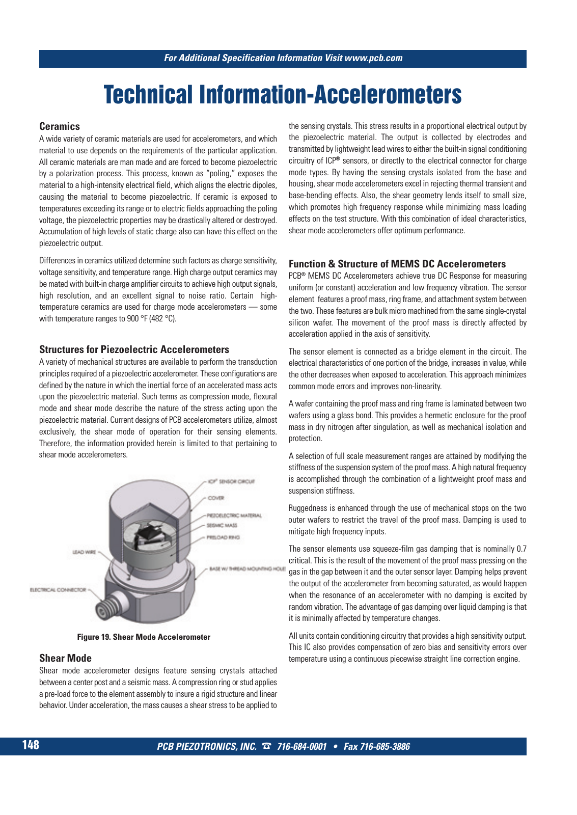
PCB PIEZOTRONICS INC 716 684 0001 Fax 716 685 3886 For Additional Specification Information Visit www pcb com 148 Technical Information Accelerometers Ceramics A wide variety of ceramic materials are used for accelerometers and which material to use depends on the requirements of the particular application All ceramic materials are man made and are forced to become piezoelectric by a polarization process This process known as poling exposes the material to a high intensity electrical field which aligns the electric dipoles causing the material to become piezoelectric If ceramic is exposed to temperatures exceeding its range or to electric fields approaching the poling voltage the piezoelectric properties may be drastically altered or destroyed Accumulation of high levels of static charge also can have this effect on the piezoelectric output Differences in ceramics utilized determine such factors as charge sensitivity voltage sensitivity and temperature range High charge output ceramics may be mated with built in charge amplifier circuits to achieve high output signals high resolution and an excellent signal to noise ratio Certain high temperature ceramics are used for charge mode accelerometers some with temperature ranges to 900 F 482 C Structures for Piezoelectric Accelerometers A variety of mechanical structures are available to perform the transduction principles required of a piezoelectric accelerometer These configurations are defined by the nature in which the inertial force of an accelerated mass acts upon the piezoelectric material Such terms as compression mode flexural mode and shear mode describe the nature of the stress acting upon the piezoelectric material Current designs of PCB accelerometers utilize almost exclusively the shear mode of operation for their sensing elements Therefore the information provided herein is limited to that pertaining to shear mode accelerometers Shear Mode Shear mode accelerometer designs feature sensing crystals attached between a center post and a seismic mass A compression ring or stud applies a pre load force to the element assembly to insure a rigid structure and linear behavior Under acceleration the mass causes a shear stress to be applied to Function Structure of MEMS DC Accelerometers PCB MEMS DC Accelerometers achieve true DC Response for measuring uniform or constant acceleration and low frequency vibration The sensor element features a proof mass ring frame and attachment system between the two These features are bulk micro machined from the same single crystal silicon wafer The movement of the proof mass is directly affected by acceleration applied in the axis of sensitivity The sensor element is connected as a bridge element in the circuit The electrical characteristics of one portion of the bridge increases in value while the other decreases when exposed to acceleration This approach minimizes common mode errors and improves non linearity A wafer containing the proof mass and ring frame is laminated between two wafers using a glass bond This provides a hermetic enclosure for the proof mass in dry nitrogen after singulation as well as mechanical isolation and protection A selection of full scale measurement ranges are attained by modifying the stiffness of the suspension system of the proof mass A high natural frequency is accomplished through the combination of a lightweight proof mass and suspension stiffness Ruggedness is enhanced through the use of mechanical stops on the two outer wafers to restrict the travel of the proof mass Damping is used to mitigate high frequency inputs The sensor elements use squeeze film gas damping that is nominally 0 7 critical This is the result of the movement of the proof mass pressing on the gas in the gap between it and the outer sensor layer Damping helps prevent the output of the accelerometer from becoming saturated as would happen when the resonance of an accelerometer with no damping is excited by random vibration The advantage of gas damping over liquid damping is that it is minimally affected by temperature changes All units contain conditioning circuitry that provides a high sensitivity output This IC also provides compensation of zero bias and sensitivity errors over temperature using a continuous piecewise straight line correction engine Figure 19 Shear Mode Accelerometer the sensing crystals This stress results in a proportional electrical output by the piezoelectric material The output is collected by electrodes and transmitted by lightweight lead wires to either the built in signal conditioning circuitry of ICP sensors or directly to the electrical connector for charge mode types By having the sensing crystals isolated from the base and housing shear mode accelerometers excel in rejecting thermal transient and base bending effects Also the shear geometry lends itself to small size which promotes high frequency response while minimizing mass loading effects on the test structure With this combination of ideal characteristics shear mode accelerometers offer optimum performance 9 T Mcatalog 2011 Seite 125 166 SYN G500 21 04 11 18 04 Seite 154