PCB Test & Measurement Seite 143
Hinweis: Dies ist eine maschinenlesbare No-Flash Ansicht.Klicken Sie hier um zur Online-Version zu gelangen.
Inhalt
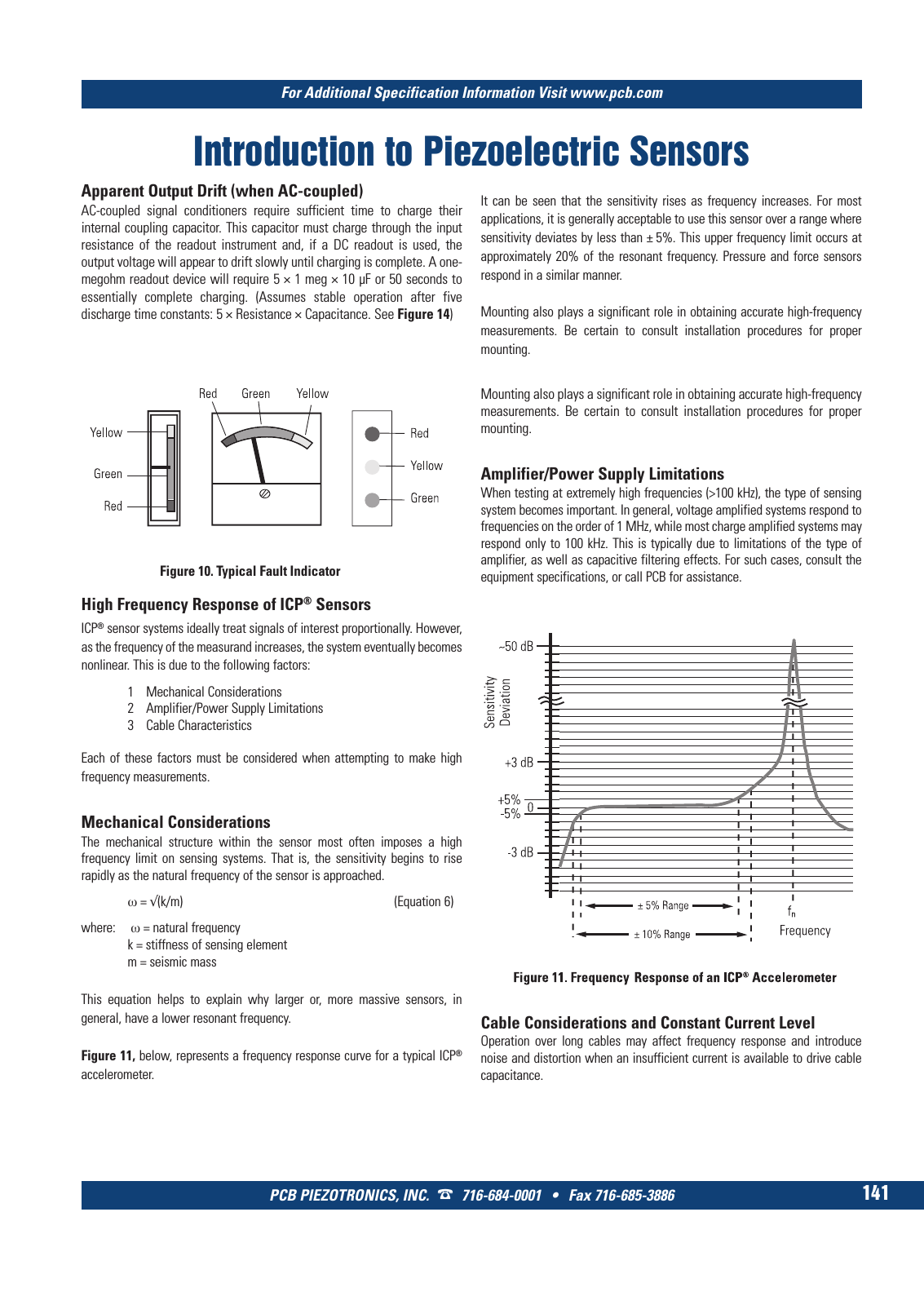
For Additional Specification Information Visit www pcb com PCB PIEZOTRONICS INC 716 684 0001 Fax 716 685 3886 141 Introduction to Piezoelectric Sensors Apparent Output Drift when AC coupled AC coupled signal conditioners require sufficient time to charge their internal coupling capacitor This capacitor must charge through the input resistance of the readout instrument and if a DC readout is used the output voltage will appear to drift slowly until charging is complete A one megohm readout device will require 5 1 meg 10 µF or 50 seconds to essentially complete charging Assumes stable operation after five discharge time constants 5 Resistance Capacitance See Figure 14 High Frequency Response of ICP Sensors ICP sensor systems ideally treat signals of interest proportionally However as the frequency of the measurand increases the system eventually becomes nonlinear This is due to the following factors 1 Mechanical Considerations 2 Amplifier Power Supply Limitations 3 Cable Characteristics Each of these factors must be considered when attempting to make high frequency measurements Mechanical Considerations The mechanical structure within the sensor most often imposes a high frequency limit on sensing systems That is the sensitivity begins to rise rapidly as the natural frequency of the sensor is approached ω k m Equation 6 where ω natural frequency k stiffness of sensing element m seismic mass This equation helps to explain why larger or more massive sensors in general have a lower resonant frequency Figure 11 below represents a frequency response curve for a typical ICP accelerometer It can be seen that the sensitivity rises as frequency increases For most applications it is generally acceptable to use this sensor over a range where sensitivity deviates by less than 5 This upper frequency limit occurs at approximately 20 of the resonant frequency Pressure and force sensors respond in a similar manner Mounting also plays a significant role in obtaining accurate high frequency measurements Be certain to consult installation procedures for proper mounting Mounting also plays a significant role in obtaining accurate high frequency measurements Be certain to consult installation procedures for proper mounting Amplifier Power Supply Limitations When testing at extremely high frequencies 100 kHz the type of sensing system becomes important In general voltage amplified systems respond to frequencies on the order of 1 MHz while most charge amplified systems may respond only to 100 kHz This is typically due to limitations of the type of amplifier as well as capacitive filtering effects For such cases consult the equipment specifications or call PCB for assistance Cable Considerations and Constant Current Level Operation over long cables may affect frequency response and introduce noise and distortion when an insufficient current is available to drive cable capacitance Figure 10 Typical Fault Indicator 9 T Mcatalog 2011 Seite 125 166 SYN G500 21 04 11 18 04 Seite 147