PCB Test & Measurement Seite 141
Hinweis: Dies ist eine maschinenlesbare No-Flash Ansicht.Klicken Sie hier um zur Online-Version zu gelangen.
Inhalt
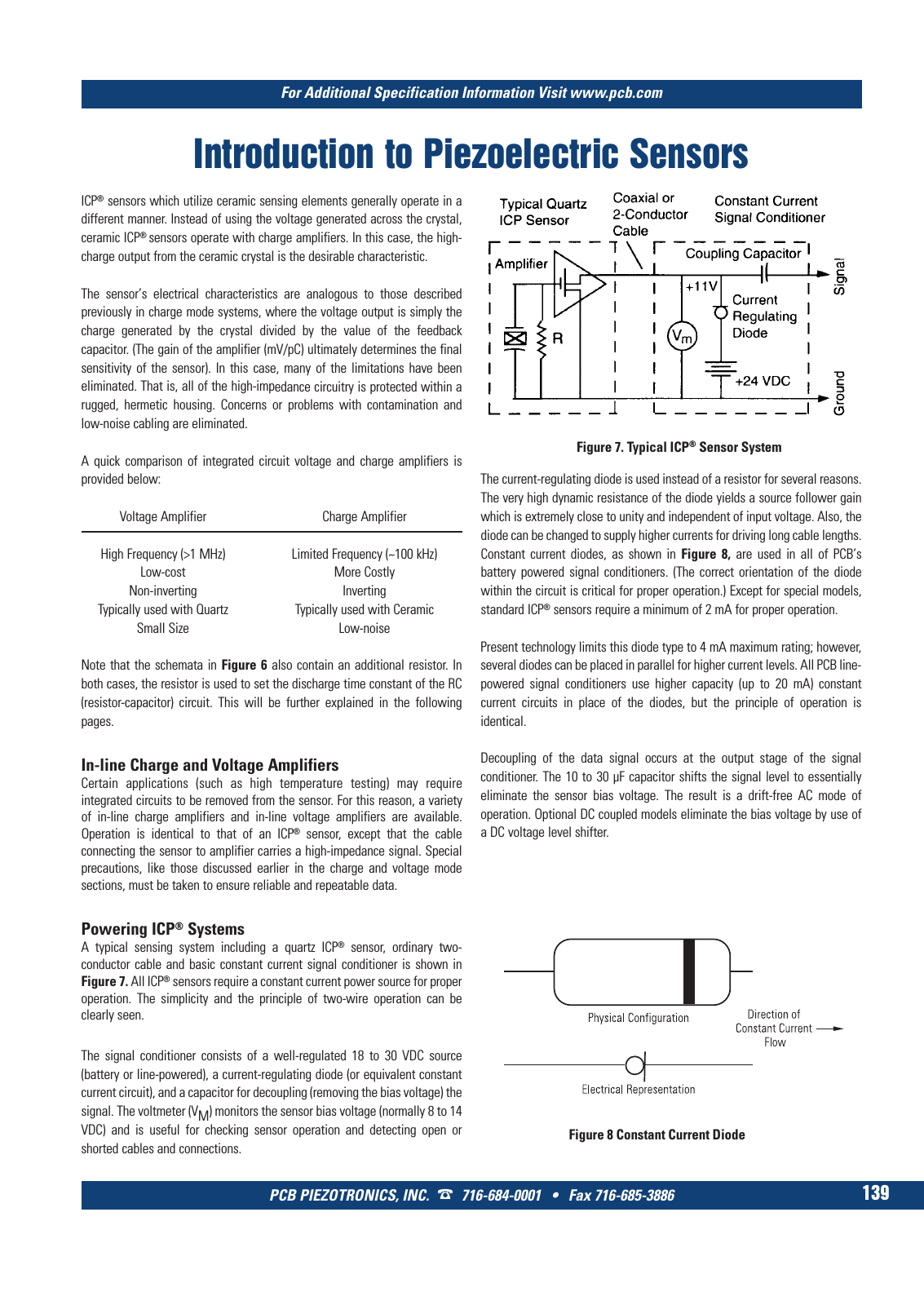
For Additional Specification Information Visit www pcb com PCB PIEZOTRONICS INC 716 684 0001 Fax 716 685 3886 139 Introduction to Piezoelectric Sensors ICP sensors which utilize ceramic sensing elements generally operate in a different manner Instead of using the voltage generated across the crystal ceramic ICP sensors operate with charge amplifiers In this case the high charge output from the ceramic crystal is the desirable characteristic The sensor s electrical characteristics are analogous to those described previously in charge mode systems where the voltage output is simply the charge generated by the crystal divided by the value of the feedback capacitor The gain of the amplifier mV pC ultimately determines the final sensitivity of the sensor In this case many of the limitations have been eliminated That is all of the high impedance circuitry is protected within a rugged hermetic housing Concerns or problems with contamination and low noise cabling are eliminated A quick comparison of integrated circuit voltage and charge amplifiers is provided below Voltage Amplifier Charge Amplifier High Frequency 1 MHz Limited Frequency 100 kHz Low cost More Costly Non inverting Inverting Typically used with Quartz Typically used with Ceramic Small Size Low noise Note that the schemata in Figure 6 also contain an additional resistor In both cases the resistor is used to set the discharge time constant of the RC resistor capacitor circuit This will be further explained in the following pages In line Charge and Voltage Amplifiers Certain applications such as high temperature testing may require integrated circuits to be removed from the sensor For this reason a variety of in line charge amplifiers and in line voltage amplifiers are available Operation is identical to that of an ICP sensor except that the cable connecting the sensor to amplifier carries a high impedance signal Special precautions like those discussed earlier in the charge and voltage mode sections must be taken to ensure reliable and repeatable data Powering ICP Systems A typical sensing system including a quartz ICP sensor ordinary two conductor cable and basic constant current signal conditioner is shown in Figure 7 All ICP sensors require a constant current power source for proper operation The simplicity and the principle of two wire operation can be clearly seen The signal conditioner consists of a well regulated 18 to 30 VDC source battery or line powered a current regulating diode or equivalent constant current circuit and a capacitor for decoupling removing the bias voltage the signal The voltmeter VM monitors the sensor bias voltage normally 8 to 14 VDC and is useful for checking sensor operation and detecting open or shorted cables and connections The current regulating diode is used instead of a resistor for several reasons The very high dynamic resistance of the diode yields a source follower gain which is extremely close to unity and independent of input voltage Also the diode can be changed to supply higher currents for driving long cable lengths Constant current diodes as shown in Figure 8 are used in all of PCB s battery powered signal conditioners The correct orientation of the diode within the circuit is critical for proper operation Except for special models standard ICP sensors require a minimum of 2 mA for proper operation Present technology limits this diode type to 4 mA maximum rating however several diodes can be placed in parallel for higher current levels All PCB line powered signal conditioners use higher capacity up to 20 mA constant current circuits in place of the diodes but the principle of operation is identical Decoupling of the data signal occurs at the output stage of the signal conditioner The 10 to 30 µF capacitor shifts the signal level to essentially eliminate the sensor bias voltage The result is a drift free AC mode of operation Optional DC coupled models eliminate the bias voltage by use of a DC voltage level shifter Figure 8 Constant Current Diode Figure 7 Typical ICP Sensor System 9 T Mcatalog 2011 Seite 125 166 SYN G500 21 04 11 18 04 Seite 145