PCB Test & Measurement Seite 140
Hinweis: Dies ist eine maschinenlesbare No-Flash Ansicht.Klicken Sie hier um zur Online-Version zu gelangen.
Inhalt
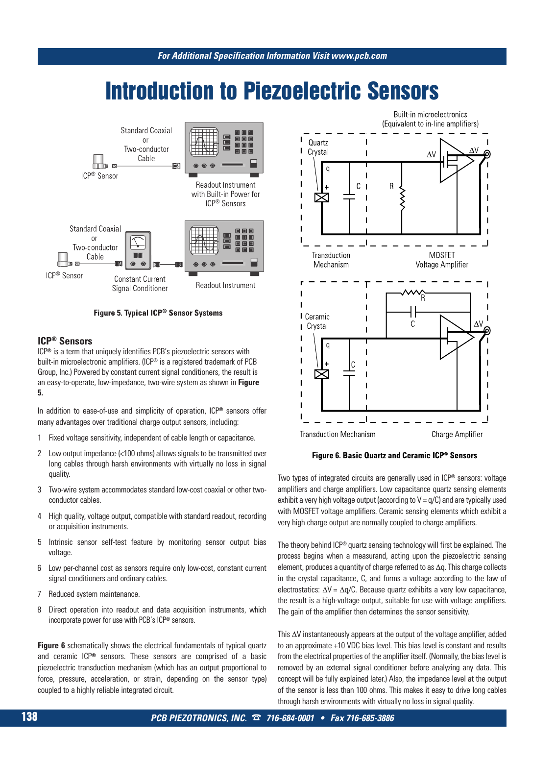
PCB PIEZOTRONICS INC 716 684 0001 Fax 716 685 3886 For Additional Specification Information Visit www pcb com 138 ICP Sensors ICP is a term that uniquely identifies PCB s piezoelectric sensors with built in microelectronic amplifiers ICP is a registered trademark of PCB Group Inc Powered by constant current signal conditioners the result is an easy to operate low impedance two wire system as shown in Figure 5 In addition to ease of use and simplicity of operation ICP sensors offer many advantages over traditional charge output sensors including 1 Fixed voltage sensitivity independent of cable length or capacitance 2 Low output impedance 100 ohms allows signals to be transmitted over long cables through harsh environments with virtually no loss in signal quality 3 Two wire system accommodates standard low cost coaxial or other two conductor cables 4 High quality voltage output compatible with standard readout recording or acquisition instruments 5 Intrinsic sensor self test feature by monitoring sensor output bias voltage 6 Low per channel cost as sensors require only low cost constant current signal conditioners and ordinary cables 7 Reduced system maintenance 8 Direct operation into readout and data acquisition instruments which incorporate power for use with PCB s ICP sensors Figure 6 schematically shows the electrical fundamentals of typical quartz and ceramic ICP sensors These sensors are comprised of a basic piezoelectric transduction mechanism which has an output proportional to force pressure acceleration or strain depending on the sensor type coupled to a highly reliable integrated circuit Two types of integrated circuits are generally used in ICP sensors voltage amplifiers and charge amplifiers Low capacitance quartz sensing elements exhibit a very high voltage output according to V q C and are typically used with MOSFET voltage amplifiers Ceramic sensing elements which exhibit a very high charge output are normally coupled to charge amplifiers The theory behind ICP quartz sensing technology will first be explained The process begins when a measurand acting upon the piezoelectric sensing element produces a quantity of charge referred to as Δq This charge collects in the crystal capacitance C and forms a voltage according to the law of electrostatics ΔV Δq C Because quartz exhibits a very low capacitance the result is a high voltage output suitable for use with voltage amplifiers The gain of the amplifier then determines the sensor sensitivity This ΔV instantaneously appears at the output of the voltage amplifier added to an approximate 10 VDC bias level This bias level is constant and results from the electrical properties of the amplifier itself Normally the bias level is removed by an external signal conditioner before analyzing any data This concept will be fully explained later Also the impedance level at the output of the sensor is less than 100 ohms This makes it easy to drive long cables through harsh environments with virtually no loss in signal quality Introduction to Piezoelectric Sensors 9 T Mcatalog 2011 Seite 125 166 SYN G500 21 04 11 18 04 Seite 144