PCB Test & Measurement Seite 139
Hinweis: Dies ist eine maschinenlesbare No-Flash Ansicht.Klicken Sie hier um zur Online-Version zu gelangen.
Inhalt
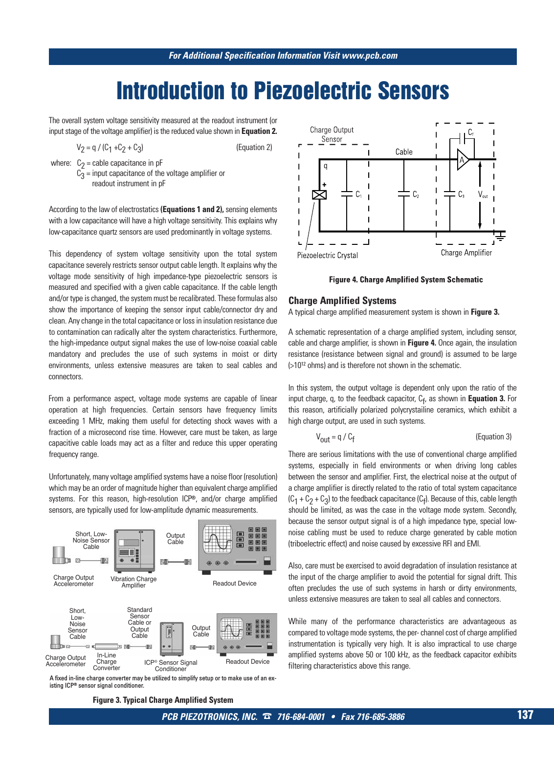
For Additional Specification Information Visit www pcb com PCB PIEZOTRONICS INC 716 684 0001 Fax 716 685 3886 137 ICP Sensor Signal Conditioner Readout Device Short Low Noise Sensor Cable Standard Sensor Cable or Output Cable Output Cable In Line Charge Converter Charge Output Accelerometer A fixed in line charge converter may be utilized to simplify setup or to make use of an ex isting ICP sensor signal conditioner Figure 3 Typical Charge Amplified System Introduction to Piezoelectric Sensors Charge Amplified Systems A typical charge amplified measurement system is shown in Figure 3 A schematic representation of a charge amplified system including sensor cable and charge amplifier is shown in Figure 4 Once again the insulation resistance resistance between signal and ground is assumed to be large 1012 ohms and is therefore not shown in the schematic In this system the output voltage is dependent only upon the ratio of the input charge q to the feedback capacitor Cf as shown in Equation 3 For this reason artificially polarized polycrystailine ceramics which exhibit a high charge output are used in such systems Vout q Cf Equation 3 There are serious limitations with the use of conventional charge amplified systems especially in field environments or when driving long cables between the sensor and amplifier First the electrical noise at the output of a charge amplifier is directly related to the ratio of total system capacitance C1 C2 C3 to the feedback capacitance Cf Because of this cable length should be limited as was the case in the voltage mode system Secondly because the sensor output signal is of a high impedance type special low noise cabling must be used to reduce charge generated by cable motion triboelectric effect and noise caused by excessive RFI and EMI Also care must be exercised to avoid degradation of insulation resistance at the input of the charge amplifier to avoid the potential for signal drift This often precludes the use of such systems in harsh or dirty environments unless extensive measures are taken to seal all cables and connectors While many of the performance characteristics are advantageous as compared to voltage mode systems the per channel cost of charge amplified instrumentation is typically very high It is also impractical to use charge amplified systems above 50 or 100 kHz as the feedback capacitor exhibits filtering characteristics above this range Vibration Charge Amplifier Readout Device Short Low Noise Sensor Cable Output Cable Charge Output Accelerometer The overall system voltage sensitivity measured at the readout instrument or input stage of the voltage amplifier is the reduced value shown in Equation 2 V2 q C1 C2 C3 Equation 2 where C2 cable capacitance in pF C3 input capacitance of the voltage amplifier or readout instrument in pF According to the law of electrostatics Equations 1 and 2 sensing elements with a low capacitance will have a high voltage sensitivity This explains why low capacitance quartz sensors are used predominantly in voltage systems This dependency of system voltage sensitivity upon the total system capacitance severely restricts sensor output cable length It explains why the voltage mode sensitivity of high impedance type piezoelectric sensors is measured and specified with a given cable capacitance If the cable length and or type is changed the system must be recalibrated These formulas also show the importance of keeping the sensor input cable connector dry and clean Any change in the total capacitance or loss in insulation resistance due to contamination can radically alter the system characteristics Furthermore the high impedance output signal makes the use of low noise coaxial cable mandatory and precludes the use of such systems in moist or dirty environments unless extensive measures are taken to seal cables and connectors From a performance aspect voltage mode systems are capable of linear operation at high frequencies Certain sensors have frequency limits exceeding 1 MHz making them useful for detecting shock waves with a fraction of a microsecond rise time However care must be taken as large capacitive cable loads may act as a filter and reduce this upper operating frequency range Unfortunately many voltage amplified systems have a noise floor resolution which may be an order of magnitude higher than equivalent charge amplified systems For this reason high resolution ICP and or charge amplified sensors are typically used for low amplitude dynamic measurements 9 T Mcatalog 2011 Seite 125 166 SYN G500 21 04 11 18 04 Seite 143