PCB Test & Measurement Seite 138
Hinweis: Dies ist eine maschinenlesbare No-Flash Ansicht.Klicken Sie hier um zur Online-Version zu gelangen.
Inhalt
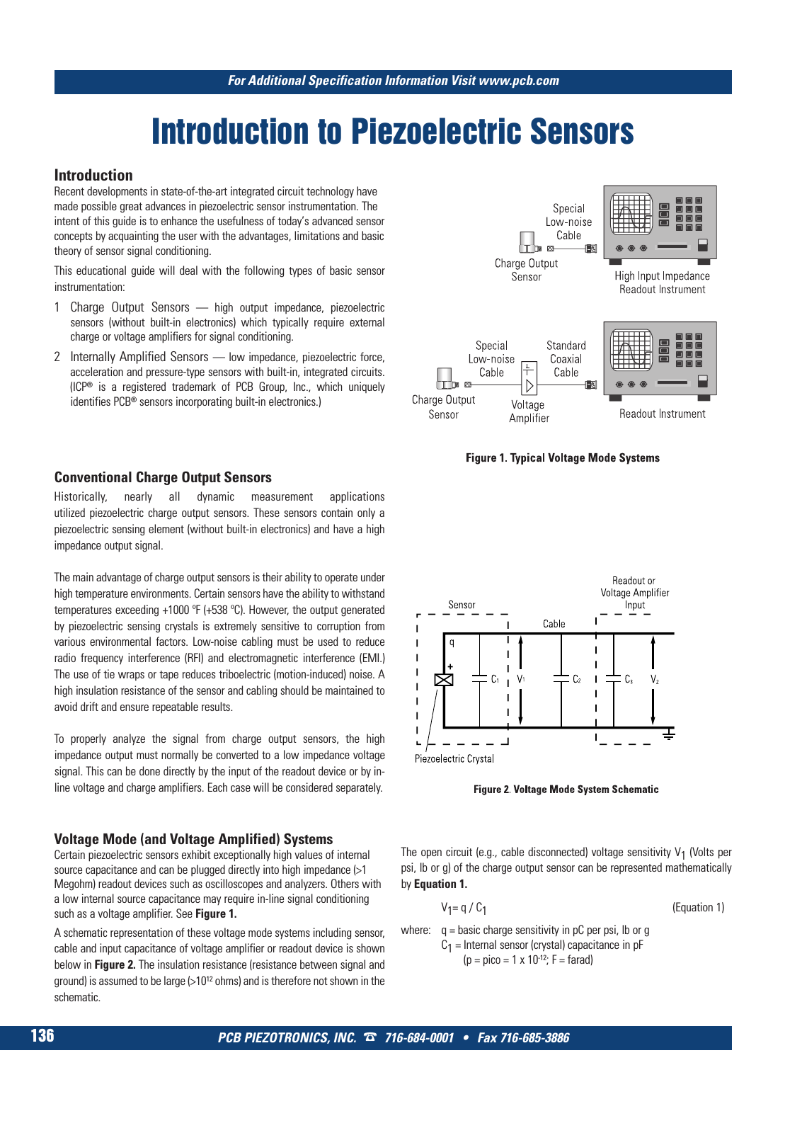
PCB PIEZOTRONICS INC 716 684 0001 Fax 716 685 3886 For Additional Specification Information Visit www pcb com 136 Introduction to Piezoelectric Sensors Introduction Recent developments in state of the art integrated circuit technology have made possible great advances in piezoelectric sensor instrumentation The intent of this guide is to enhance the usefulness of today s advanced sensor concepts by acquainting the user with the advantages limitations and basic theory of sensor signal conditioning This educational guide will deal with the following types of basic sensor instrumentation 1 Charge Output Sensors high output impedance piezoelectric sensors without built in electronics which typically require external charge or voltage amplifiers for signal conditioning 2 Internally Amplified Sensors low impedance piezoelectric force acceleration and pressure type sensors with built in integrated circuits ICP is a registered trademark of PCB Group Inc which uniquely identifies PCB sensors incorporating built in electronics Conventional Charge Output Sensors Historically nearly all dynamic measurement applications utilized piezoelectric charge output sensors These sensors contain only a piezoelectric sensing element without built in electronics and have a high impedance output signal The main advantage of charge output sensors is their ability to operate under high temperature environments Certain sensors have the ability to withstand temperatures exceeding 1000 ºF 538 ºC However the output generated by piezoelectric sensing crystals is extremely sensitive to corruption from various environmental factors Low noise cabling must be used to reduce radio frequency interference RFI and electromagnetic interference EMI The use of tie wraps or tape reduces triboelectric motion induced noise A high insulation resistance of the sensor and cabling should be maintained to avoid drift and ensure repeatable results To properly analyze the signal from charge output sensors the high impedance output must normally be converted to a low impedance voltage signal This can be done directly by the input of the readout device or by in line voltage and charge amplifiers Each case will be considered separately Voltage Mode and Voltage Amplified Systems Certain piezoelectric sensors exhibit exceptionally high values of internal source capacitance and can be plugged directly into high impedance 1 Megohm readout devices such as oscilloscopes and analyzers Others with a low internal source capacitance may require in line signal conditioning such as a voltage amplifier See Figure 1 A schematic representation of these voltage mode systems including sensor cable and input capacitance of voltage amplifier or readout device is shown below in Figure 2 The insulation resistance resistance between signal and ground is assumed to be large 1012 ohms and is therefore not shown in the schematic The open circuit e g cable disconnected voltage sensitivity V1 Volts per psi lb or g of the charge output sensor can be represented mathematically by Equation 1 V1 q C1 Equation 1 where q basic charge sensitivity in pC per psi lb or g C1 Internal sensor crystal capacitance in pF p pico 1 x 10 12 F farad 9 T Mcatalog 2011 Seite 125 166 SYN G500 21 04 11 18 04 Seite 142