PCB Test & Measurement Seite 123
Hinweis: Dies ist eine maschinenlesbare No-Flash Ansicht.Klicken Sie hier um zur Online-Version zu gelangen.
Inhalt
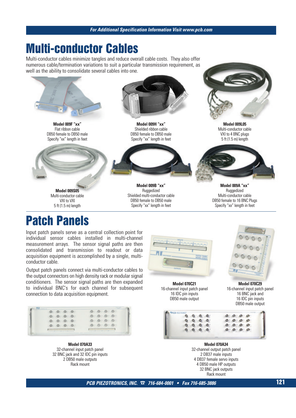
For Additional Specification Information Visit www pcb com PCB PIEZOTRONICS INC 716 684 0001 Fax 716 685 3886 121 Multi conductor Cables Model 009F xx Flat ribbon cable DB50 female to DB50 male Specify xx length in feet Model 009A xx Ruggedized Multi conductor cable DB50 female to 16 BNC Plugs Specify xx length in feet Model 009S05 Multi conductor cable VXI to VXI 5 ft 1 5 m length Multi conductor cables minimize tangles and reduce overall cable costs They also offer numerous cable termination variations to suit a particular transmission requirement as well as the ability to consolidate several cables into one Model 009B xx Ruggedized Shielded multi conductor cable DB50 female to DB50 male Specify xx length in feet Patch Panels Model 070C21 16 channel input patch panel 16 IDC pin inputs DB50 male output Model 070C29 16 channel input patch panel 16 BNC jack and 16 IDC pin inputs DB50 male output Model 070A33 32 channel input patch panel 32 BNC jack and 32 IDC pin inputs 2 DB50 male outputs Rack mount Model 070A34 32 channel output patch panel 2 DB37 male inputs 4 DB37 female servo inputs 4 DB50 male HP outputs 32 BNC jack outputs Rack mount Input patch panels serve as a central collection point for individual sensor cables installed in multi channel measurement arrays The sensor signal paths are then consolidated and transmission to readout or data acquisition equipment is accomplished by a single multi conductor cable Output patch panels connect via multi conductor cables to the output connectors on high density rack or modular signal conditioners The sensor signal paths are then expanded to individual BNC s for each channel for subsequent connection to data acquisition equipment Model 009H xx Shielded ribbon cable DB50 female to DB50 male Specify xx length in feet Model 009L05 Multi conductor cable VXI to 4 BNC plugs 5 ft 1 5 m length 8 T Mcatalog 2011 Seite 109 124 SYN G500 21 04 11 18 01 Seite 127