PCB Test & Measurement Seite 115
Hinweis: Dies ist eine maschinenlesbare No-Flash Ansicht.Klicken Sie hier um zur Online-Version zu gelangen.
Inhalt
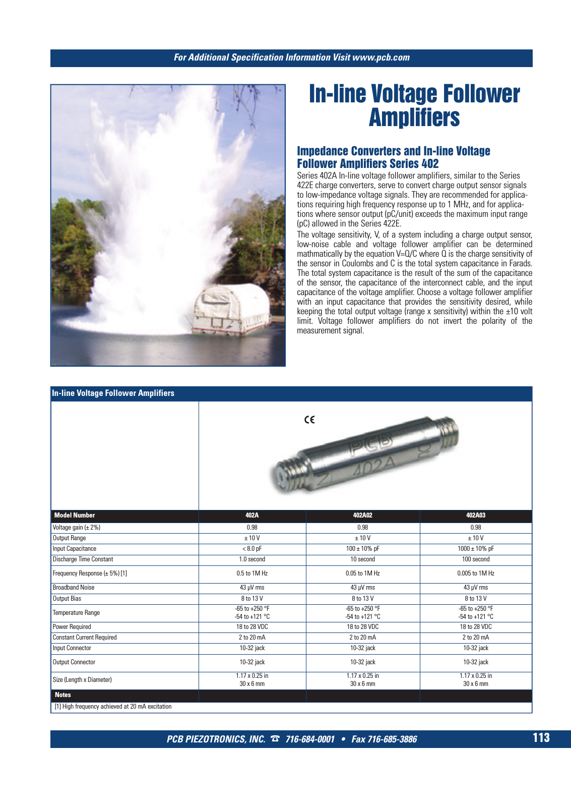
For Additional Specification Information Visit www pcb com PCB PIEZOTRONICS INC 716 684 0001 Fax 716 685 3886 113 In line Voltage Follower Amplifiers In line Voltage Follower Amplifiers Model Number 402A 402A02 402A03 Voltage gain 2 0 98 0 98 0 98 Output Range 10 V 10 V 10 V Input Capacitance 8 0 pF 100 10 pF 1000 10 pF Discharge Time Constant 1 0 second 10 second 100 second Frequency Response 5 1 0 5 to 1M Hz 0 05 to 1M Hz 0 005 to 1M Hz Broadband Noise 43 µV rms 43 µV rms 43 µV rms Output Bias 8 to 13 V 8 to 13 V 8 to 13 V Temperature Range 65 to 250 F 54 to 121 C 65 to 250 F 54 to 121 C 65 to 250 F 54 to 121 C Power Required 18 to 28 VDC 18 to 28 VDC 18 to 28 VDC Constant Current Required 2 to 20 mA 2 to 20 mA 2 to 20 mA Input Connector 10 32 jack 10 32 jack 10 32 jack Output Connector 10 32 jack 10 32 jack 10 32 jack Size Length x Diameter 1 17 x 0 25 in30 x 6 mm 1 17 x 0 25 in 30 x 6 mm 1 17 x 0 25 in 30 x 6 mm Notes 1 High frequency achieved at 20 mA excitation Impedance Converters and In line Voltage Follower Amplifiers Series 402 Series 402A In line voltage follower amplifiers similar to the Series 422E charge converters serve to convert charge output sensor signals to low impedance voltage signals They are recommended for applica tions requiring high frequency response up to 1 MHz and for applica tions where sensor output pC unit exceeds the maximum input range pC allowed in the Series 422E The voltage sensitivity V of a system including a charge output sensor low noise cable and voltage follower amplifier can be determined mathmatically by the equation V Q C where Q is the charge sensitivity of the sensor in Coulombs and C is the total system capacitance in Farads The total system capacitance is the result of the sum of the capacitance of the sensor the capacitance of the interconnect cable and the input capacitance of the voltage amplifier Choose a voltage follower amplifier with an input capacitance that provides the sensitivity desired while keeping the total output voltage range x sensitivity within the 10 volt limit Voltage follower amplifiers do not invert the polarity of the measurement signal 8 T Mcatalog 2011 Seite 109 124 SYN G500 21 04 11 18 01 Seite 119