PCB Test & Measurement Seite 109
Hinweis: Dies ist eine maschinenlesbare No-Flash Ansicht.Klicken Sie hier um zur Online-Version zu gelangen.
Inhalt
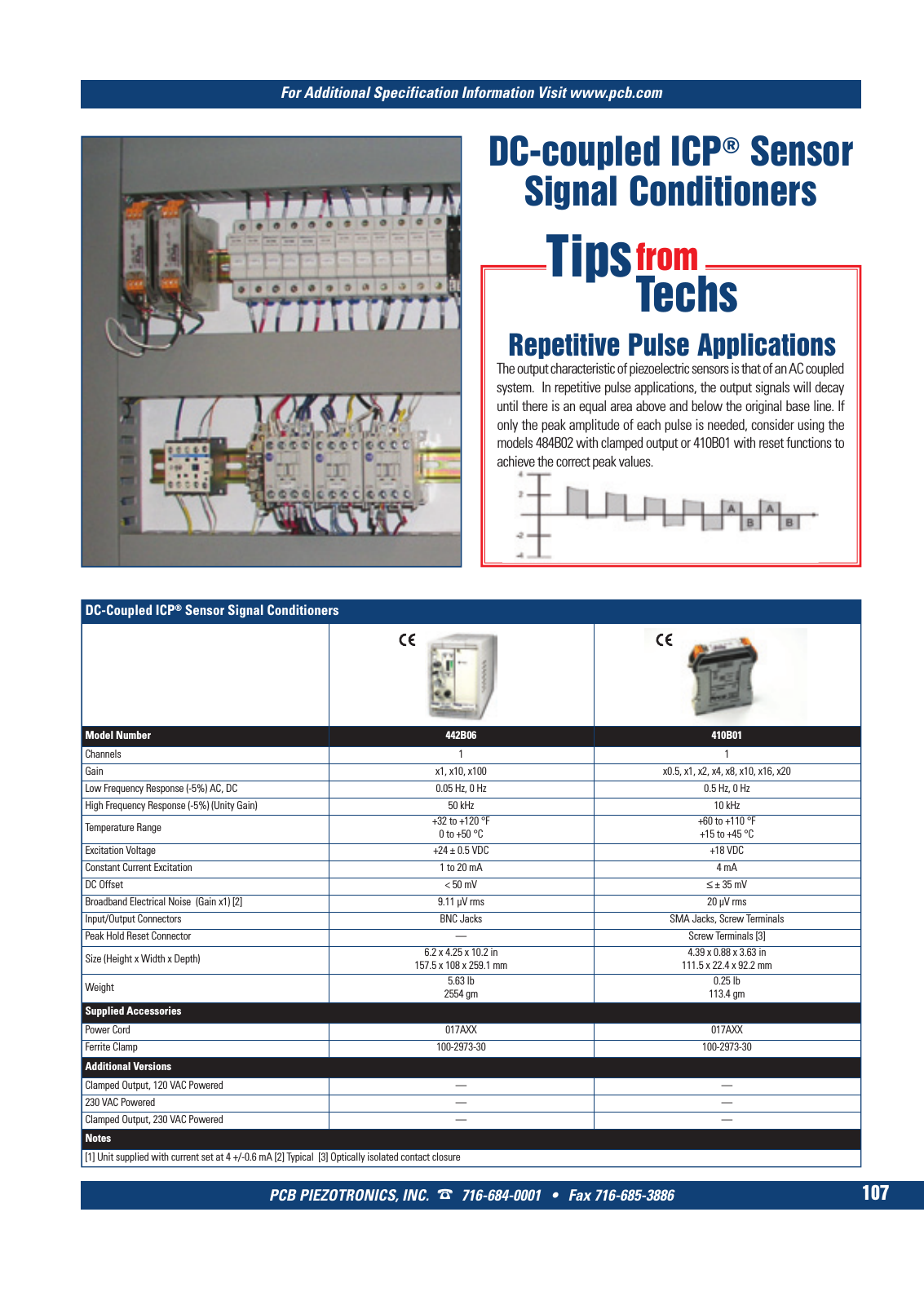
For Additional Specification Information Visit www pcb com PCB PIEZOTRONICS INC 716 684 0001 Fax 716 685 3886 107 DC coupled ICP Sensor Signal Conditioners DC Coupled ICP Sensor Signal Conditioners Model Number 442B06 410B01 Channels 1 1 Gain x1 x10 x100 x0 5 x1 x2 x4 x8 x10 x16 x20 Low Frequency Response 5 AC DC 0 05 Hz 0 Hz 0 5 Hz 0 Hz High Frequency Response 5 Unity Gain 50 kHz 10 kHz Temperature Range 32 to 120 F0 to 50 C 60 to 110 F 15 to 45 C Excitation Voltage 24 0 5 VDC 18 VDC Constant Current Excitation 1 to 20 mA 4 mA DC Offset 50 mV 35 mV Broadband Electrical Noise Gain x1 2 9 11 µV rms 20 µV rms Input Output Connectors BNC Jacks SMA Jacks Screw Terminals Peak Hold Reset Connector Screw Terminals 3 Size Height x Width x Depth 6 2 x 4 25 x 10 2 in157 5 x 108 x 259 1 mm 4 39 x 0 88 x 3 63 in 111 5 x 22 4 x 92 2 mm Weight 5 63 lb2554 gm 0 25 lb 113 4 gm Supplied Accessories Power Cord 017AXX 017AXX Ferrite Clamp 100 2973 30 100 2973 30 Additional Versions Clamped Output 120 VAC Powered 230 VAC Powered Clamped Output 230 VAC Powered Notes 1 Unit supplied with current set at 4 0 6 mA 2 Typical 3 Optically isolated contact closure Repetitive Pulse Applications The output characteristic of piezoelectric sensors is that of an AC coupled system In repetitive pulse applications the output signals will decay until there is an equal area above and below the original base line If only the peak amplitude of each pulse is needed consider using the models 484B02 with clamped output or 410B01 with reset functions to achieve the correct peak values Tipsfrom Techs 7 T Mcatalog 2011 Seite 99 108 SYN G500 21 04 11 17 58 Seite 107