IMI Industrial Vibration Sensors Katalog Seite 25
Hinweis: Dies ist eine maschinenlesbare No-Flash Ansicht.Klicken Sie hier um zur Online-Version zu gelangen.
Inhalt
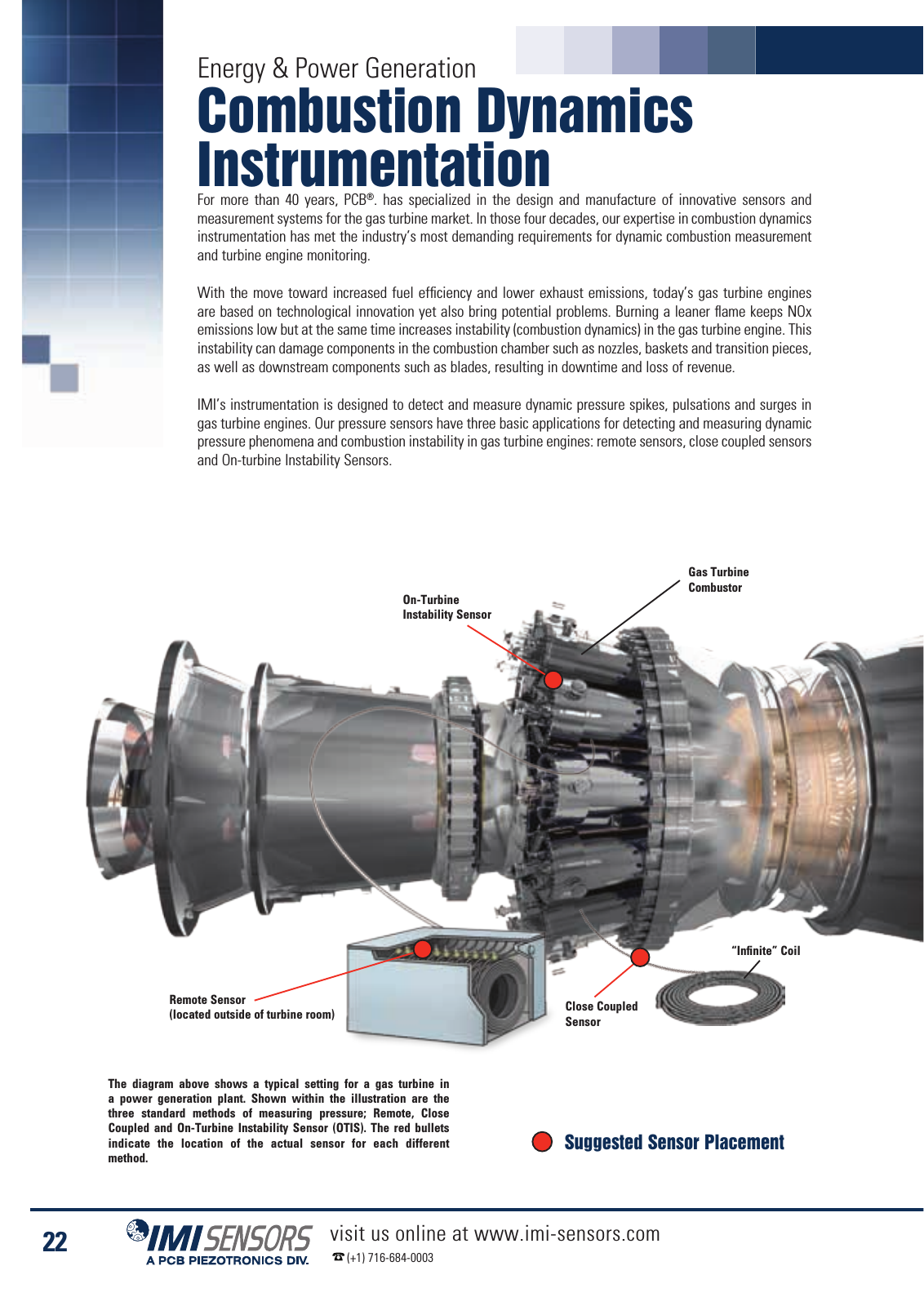
The diagram above shows a typical setting for a gas turbine in a power generation plant Shown within the illustration are the three standard methods of measuring pressure Remote Close Coupled and On Turbine Instability Sensor OTIS The red bullets indicate the location of the actual sensor for each different method On Turbine Instability Sensor Gas Turbine Combustor Infinite Coil Remote Sensor located outside of turbine room Close Coupled Sensor Energy Power Generation Combustion Dynamics Instrumentation For more than 40 years PCB has specialized in the design and manufacture of innovative sensors and measurement systems for the gas turbine market In those four decades our expertise in combustion dynamics instrumentation has met the industry s most demanding requirements for dynamic combustion measurement and turbine engine monitoring With the move toward increased fuel efficiency and lower exhaust emissions today s gas turbine engines are based on technological innovation yet also bring potential problems Burning a leaner flame keeps NOx emissions low but at the same time increases instability combustion dynamics in the gas turbine engine This instability can damage components in the combustion chamber such as nozzles baskets and transition pieces as well as downstream components such as blades resulting in downtime and loss of revenue IMI s instrumentation is designed to detect and measure dynamic pressure spikes pulsations and surges in gas turbine engines Our pressure sensors have three basic applications for detecting and measuring dynamic pressure phenomena and combustion instability in gas turbine engines remote sensors close coupled sensors and On turbine Instability Sensors Suggested Sensor Placement 22 visit us online at www imi sensors com 1 716 684 0003