PCB Test & Measurement Seite 146
Hinweis: Dies ist eine maschinenlesbare No-Flash Ansicht.Klicken Sie hier um zur Online-Version zu gelangen.
Inhalt
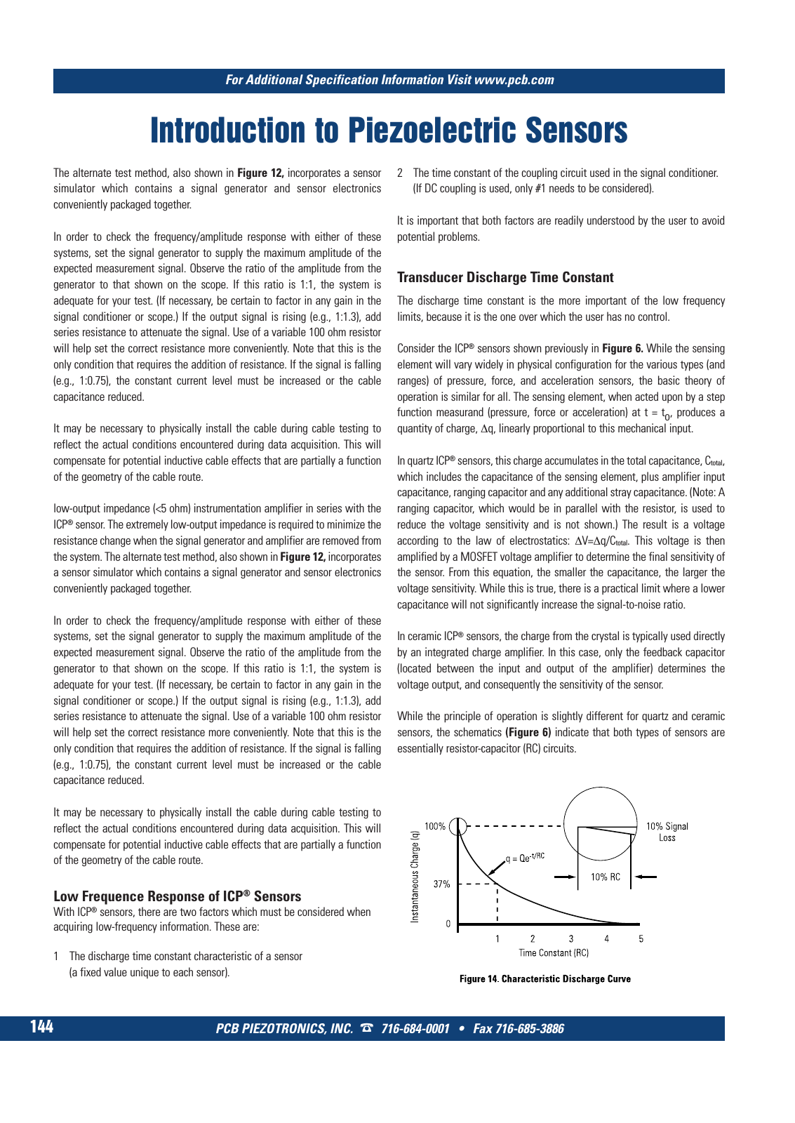
PCB PIEZOTRONICS INC 716 684 0001 Fax 716 685 3886 For Additional Specification Information Visit www pcb com 144 Introduction to Piezoelectric Sensors The alternate test method also shown in Figure 12 incorporates a sensor simulator which contains a signal generator and sensor electronics conveniently packaged together In order to check the frequency amplitude response with either of these systems set the signal generator to supply the maximum amplitude of the expected measurement signal Observe the ratio of the amplitude from the generator to that shown on the scope If this ratio is 1 1 the system is adequate for your test If necessary be certain to factor in any gain in the signal conditioner or scope If the output signal is rising e g 1 1 3 add series resistance to attenuate the signal Use of a variable 100 ohm resistor will help set the correct resistance more conveniently Note that this is the only condition that requires the addition of resistance If the signal is falling e g 1 0 75 the constant current level must be increased or the cable capacitance reduced It may be necessary to physically install the cable during cable testing to reflect the actual conditions encountered during data acquisition This will compensate for potential inductive cable effects that are partially a function of the geometry of the cable route low output impedance 5 ohm instrumentation amplifier in series with the ICP sensor The extremely low output impedance is required to minimize the resistance change when the signal generator and amplifier are removed from the system The alternate test method also shown in Figure 12 incorporates a sensor simulator which contains a signal generator and sensor electronics conveniently packaged together In order to check the frequency amplitude response with either of these systems set the signal generator to supply the maximum amplitude of the expected measurement signal Observe the ratio of the amplitude from the generator to that shown on the scope If this ratio is 1 1 the system is adequate for your test If necessary be certain to factor in any gain in the signal conditioner or scope If the output signal is rising e g 1 1 3 add series resistance to attenuate the signal Use of a variable 100 ohm resistor will help set the correct resistance more conveniently Note that this is the only condition that requires the addition of resistance If the signal is falling e g 1 0 75 the constant current level must be increased or the cable capacitance reduced It may be necessary to physically install the cable during cable testing to reflect the actual conditions encountered during data acquisition This will compensate for potential inductive cable effects that are partially a function of the geometry of the cable route Low Frequence Response of ICP Sensors With ICP sensors there are two factors which must be considered when acquiring low frequency information These are 1 The discharge time constant characteristic of a sensor a fixed value unique to each sensor Transducer Discharge Time Constant The discharge time constant is the more important of the low frequency limits because it is the one over which the user has no control Consider the ICP sensors shown previously in Figure 6 While the sensing element will vary widely in physical configuration for the various types and ranges of pressure force and acceleration sensors the basic theory of operation is similar for all The sensing element when acted upon by a step function measurand pressure force or acceleration at t to produces a quantity of charge Δq linearly proportional to this mechanical input In quartz ICP sensors this charge accumulates in the total capacitance Ctotal which includes the capacitance of the sensing element plus amplifier input capacitance ranging capacitor and any additional stray capacitance Note A ranging capacitor which would be in parallel with the resistor is used to reduce the voltage sensitivity and is not shown The result is a voltage according to the law of electrostatics ΔV Δq Ctotal This voltage is then amplified by a MOSFET voltage amplifier to determine the final sensitivity of the sensor From this equation the smaller the capacitance the larger the voltage sensitivity While this is true there is a practical limit where a lower capacitance will not significantly increase the signal to noise ratio In ceramic ICP sensors the charge from the crystal is typically used directly by an integrated charge amplifier In this case only the feedback capacitor located between the input and output of the amplifier determines the voltage output and consequently the sensitivity of the sensor While the principle of operation is slightly different for quartz and ceramic sensors the schematics Figure 6 indicate that both types of sensors are essentially resistor capacitor RC circuits 2 The time constant of the coupling circuit used in the signal conditioner If DC coupling is used only 1 needs to be considered It is important that both factors are readily understood by the user to avoid potential problems 9 T Mcatalog 2011 Seite 125 166 SYN G500 21 04 11 18 04 Seite 150